

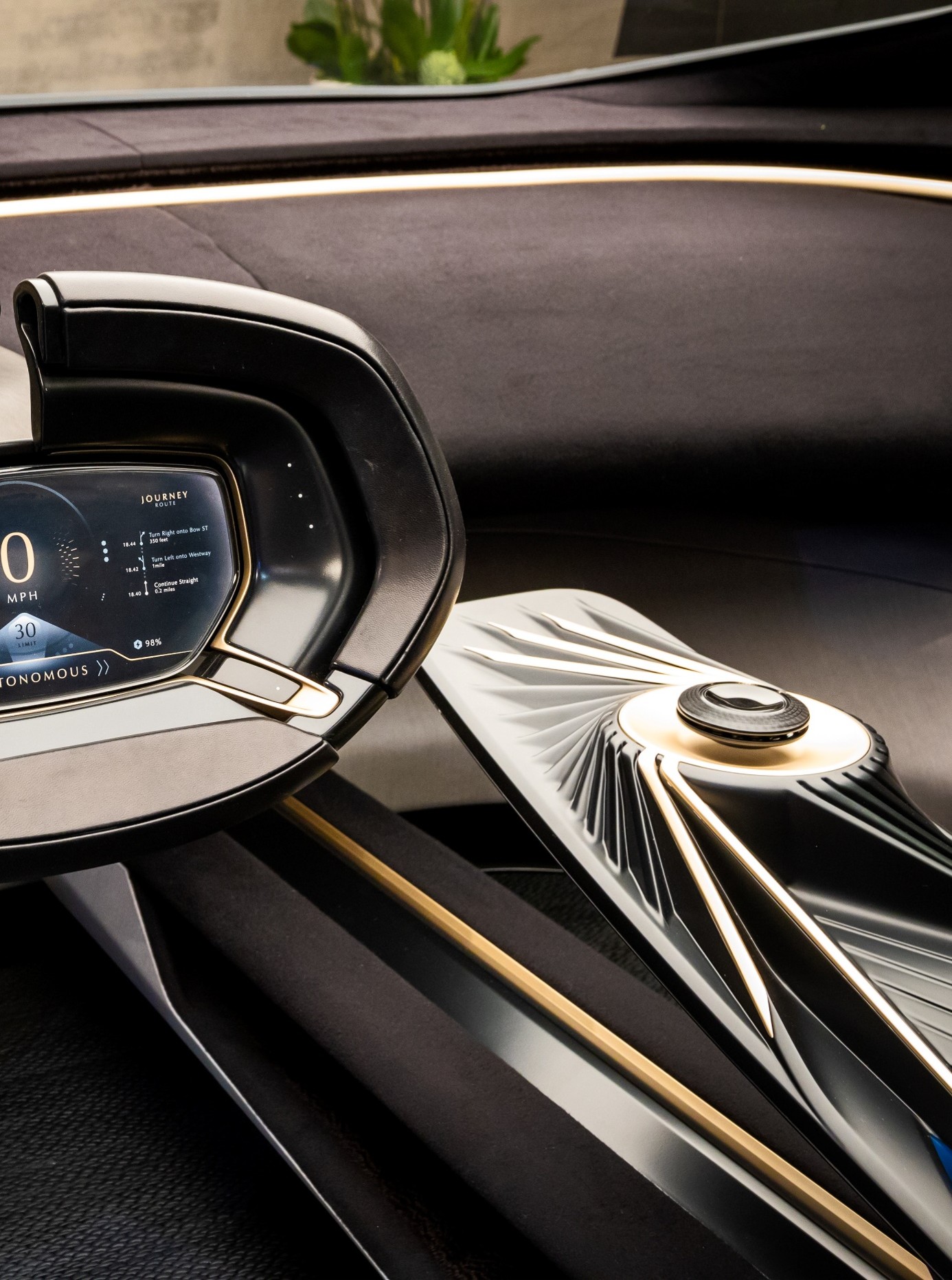
As the number of available vehicle functions continues to increase, automotive human-machine interfaces are becoming more adaptive and interactive. Touchscreens are now widely used, yet mechanical controls remain valued for their intuitive operation, even though their functions are generally limited. To enrich user interaction through haptic feedback, MMT has developed an electromagnetic solution capable of producing multiple tactile sensations in rotary HMI controls.
HMI in vehicle interiors
The expansion of user-centred functions has made the passenger compartment a key component of the overall in-vehicle experience. Rather than serving only as a functional control environment, the cabin is increasingly expected to accommodate individual preferences while integrating a large number of features seamlessly. Digital displays are already common in dashboards, and other interfaces are following the same direction through the adoption of touchscreens and smart surfaces.
The progressive removal of physical buttons from recent vehicle platforms has generated significant debate among both designers and users. Although this approach produces cleaner and more streamlined interfaces, it can also introduce a safety concern: without physical references, drivers may need to look away from the road to select the intended command. [1][2] Haptic feedback can help limit this issue by conveying information directly through touch, while also creating more intuitive and tactile interactions inside the vehicle.
Nevertheless, flat surfaces remain poorly suited to genuine eyes-free operation. Knobs and push-buttons therefore continue to be used in vehicle cabins, although in reduced numbers. As fewer physical controls remain, each one is increasingly expected to manage several functions and to provide mode-specific feedback. [3]
A typical example is the central rotary controller used to operate an infotainment system. A single control may provide access to audio, navigation and HVAC functions. In most current implementations, however, the mechanism is entirely passive and relies on a basic mechanical detent system, so the tactile response cannot be adjusted according to the selected function.
Drawing on more than three decades of mechatronics expertise, MMT has developed an electromagnetic device built around a switchable magnet, also referred to as an Electro-Permanent Magnet (EPM), to improve the behaviour of rotary HMI controls. [4] The objective is to achieve silent operation, negligible wear and virtually zero power consumption during most of the operating cycle.
EPM operating principle
In its simplest form, an EPM combines a magnet with a coil. A calibrated current pulse applied to the coil changes the magnetization state of the magnet. Materials with low coercivity are particularly suitable because their magnetization direction can be fully reversed more easily.
Completely demagnetizing such a material is more difficult because of its nonlinear magnetic behaviour. A comparable result can nevertheless be obtained by adding a bias magnet.

Figure 1: Electro-Permanent Magnet incorporating a bias magnet
As illustrated in Figure 1, the MMT configuration includes the following elements:
- A first magnet manufactured from a low-coercivity material;
- A coil wound around the low-coercivity magnet;
- A second, high-coercivity magnet acting as the bias magnet;
- Soft-ferromagnetic components surrounding the two magnets and completing the magnetic circuit.
The two magnets are magnetized along the direction defined by the surrounding ferromagnetic components. The low-coercivity magnet, typically made from AlNiCo, can have its polarity reversed by an externally generated magnetic field. By contrast, the high-coercivity magnet, generally NdFeB, retains a fixed polarity.
The EPM therefore operates as a magnetic-flux switch. Two stable states are obtained according to the polarity of the low-coercivity magnet:
- When the two magnets have opposite magnetization directions (Figure 1, OFF state), the flux remains confined within the ferromagnetic structure. The magnetic circuit is effectively short-circuited inside the EPM, and the assembly behaves as a magnetically inactive component.
- When both magnets are magnetized in the same direction (Figure 1, ON state), the flux can no longer remain entirely within the ferromagnetic path. It leaves the assembly and closes through the surrounding air, thereby generating an external magnetic field.
Both configurations are stable. Transition from one state to the other is achieved by energizing the coil briefly, which reverses the magnetization of the AlNiCo element. The EPM can thus be switched electrically between active and inactive states, while consuming energy only during the short pulse required for the transition.
Precise control of the current pulse also makes it possible to position the AlNiCo magnet anywhere below magnetic saturation. Consequently, the EPM is not limited to binary ON/OFF behaviour: the intensity of the external field can be adjusted as required. This capability is particularly valuable when the magnetic interaction with the surrounding structure must be varied.
MMT EPM-based haptic technology
The haptic solution developed by MMT comprises two main parts:
- A stator (Figure 2, Toothed EPM stator) based on an EPM, with teeth distributed around the outside diameter of the ferromagnetic structure;
- A rotor (Figure 2, Toothed Rotor device) formed by a ferromagnetic ring placed around the EPM, with teeth distributed along its inner diameter.

Figure 2: Example of the MMT haptic device
Depending on the EPM state, the complete assembly shown in Figure 2 (MMT haptic device) exhibits two principal operating modes:
- In free-wheel mode, the magnetic flux remains inside the EPM (blue curve in Figure 3). The stator and rotor do not interact magnetically, allowing the rotor to turn freely.
- In ratchet mode, modulation of the magnetic flux generates a detent effect (orange curve in Figure 3). The flux crosses the air gap and is collected by the rotor ring. As the rotor moves, the relative alignment of the stator and rotor teeth changes the local air-gap length and therefore modulates the flux path. The resulting magnetic torque reproduces a sensation comparable to mechanical detents.

Figure 3: Simulated free-wheel and ratchet torque of an EPM device
Because the EPM retains its magnetic state, the haptic unit remains in free-wheel or ratchet mode without additional energy input. Between switching events, it behaves as a passive system. This differs from motor-based or magnetorheological-fluid solutions, which generally require continuous electrical power during operation.
The technology can, for example, be integrated into a rotary knob. Combined with suitable control electronics, the interface can be commanded to alternate between unrestricted rotation and a stepped operating mode.
Haptic signature
The tactile response of an HMI device can contribute to a brand-specific user experience. The cogging-torque profile is therefore deliberately shaped through the magnetic design, particularly by adjusting the geometry and number of teeth on both the stator and the rotor.
Figure 4 compares torque profiles produced by two different tooth geometries. Although the overall shapes are similar, the profile shown on the right provides a smoother transition from one detent to the next.

Figure 4: Two haptic signatures for a 12-position device
These torque profiles can be optimized using finite-element-method (FEM) simulations, but such calculations demand substantial computational resources and processing time. To assess a large number of tooth geometries more rapidly, MMT developed an in-house permeance-network model of the device. The model provides results that correlate satisfactorily with three-dimensional FEM simulations. [5]
Real-time variability
A major advantage of this technology is the combination of adjustable haptic behaviour and low energy consumption. As described above, only a small current pulse is needed to change between free-wheel and detent modes. The EPM field, and therefore the torque level, can also be tuned by controlling the degree of saturation reached by the low-coercivity magnet during polarization. A controlled current pulse can thus set the magnetic detents to a selected strength, providing an additional degree of freedom for the HMI knob.

Figure 5: Four torque levels obtained from different polarization levels of the low-coercivity magnet
The concept can be extended further by integrating a position sensor. This enables real-time programming of the EPM effect from any angular position. Individual detents can then be modified or disabled, opening up several additional functions, including:
- Changing the number of detents within one revolution (Figure 5, Half detent, Medium torque);
- Applying a progressive torque variation over a defined angular travel.
This approach is particularly appropriate for multifunction interfaces such as infotainment controllers, where one physical device is used to manipulate several graphical user-interface elements. A specific mechanical response can therefore be assigned to each function.
The same capability can be used to create a hard-stop effect. Such a function is commonly incorporated as a safety feature in rotary gear selectors to prevent unintended commands. Similar feedback can also indicate that the limit of a selected function has been reached, for example the end of a temperature or volume range.
Conventional hard stops are generally mechanical. They require additional packaging space and may produce audible noise during use. MMT therefore investigated several electromechanical approaches that could provide this function with minimal impact on the EPM assembly. The most direct solution consisted in optimizing the initial topology to generate a much higher magnetic torque within the available volume. In the example shown in Figure 5, the highest torque level represents the hard stop, whereas the lowest level corresponds to normal operation. The interface would consequently operate at low torque during regular use and switch to maximum torque only when a hard stop is required.
Application examples
The concept is scalable and has been implemented successfully in rotary knobs and scroll wheels with diameters ranging from less than 20 mm to more than 80 mm (Figure 6).

Figure 6: Demonstrators developed by MMT
A hollow-centre configuration can be selected either for styling purposes or to accommodate mechanical elements such as a central shaft, as well as wiring for additional electronics located above the knob. Thanks to its compact architecture, the device can also be combined with other functions, including joystick operation or a small display positioned at the centre.
Potential cockpit applications include the various rotary controls used throughout the cabin, such as central-console infotainment knobs, steering-wheel menu selectors and HVAC controls.
Conclusion
The growing use of touch-sensitive surfaces has substantially reduced the number of mechanical controls in modern vehicle interiors. The physical interfaces that remain are increasingly multifunctional, yet they often provide insufficiently differentiated feedback for users to identify the active function through touch alone. Although haptic effects are now common in tablets and touchscreens, rotary controls still offer limited tactile variability. MMT addresses this gap with an EPM-based haptic device designed for rotary HMI applications. This solid-state solution changes silently between several tactile behaviours, ranging from free rotation to detents that can be programmed dynamically.
Author

Antoine Delaporte is Sensors & Direct-Drive Actuators R&D Engineer at Moving Magnet Technologies (MMT) S.A. in Besançon (France)