

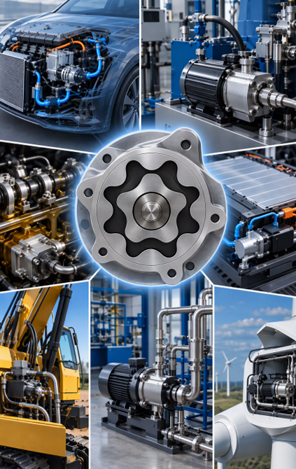
This paper investigates an innovative approach to integrating a gerotor positive-displacement pump directly within a flux-switching permanent-magnet motor. The proposed architecture was developed through an optimization process supported by both two-dimensional and three-dimensional numerical simulations. A functional prototype was subsequently manufactured and experimentally characterized. Its performance was then assessed against that of a conventional motor architecture, providing experimental validation of the proposed concept.
Keywords – flux-switching motor, gerotor pump, positive-displacement pump, compact integration
I. INTRODUCTION
The transition toward battery electric vehicles (BEVs) is increasing the demand for systems that combine reduced weight and volume with high energy efficiency. Although electric propulsion is generally associated with traction motors delivering several hundred kilowatts, a modern electric vehicle also incorporates numerous auxiliary electric motors operating for extended periods.
Among these auxiliary systems are pumps responsible for thermal management of the battery, power electronics and drivetrain, as well as systems used for climate control. Some of these functions remain active not only while the vehicle is moving but also during battery charging. Because their operating energy cannot be recovered through regeneration and because their cumulative operating time may reach thousands of hours, improving their efficiency represents an important engineering objective.
In addition to efficiency, automotive pumps must provide high reliability and low acoustic emissions. Noise is particularly important in electric vehicles because pump operation can become clearly perceptible when propulsion-related noise is absent, for example when the vehicle is stationary.
The purpose of this work is therefore to investigate a new architecture in which the pumping function is directly incorporated into an electric motor. The performance obtained from a manufactured prototype is also evaluated experimentally.
The following sections first introduce the selected gerotor pumping technology before describing its integration within the electric motor. The choice of motor topology is then discussed, highlighting the potential advantages of a flux-switching permanent-magnet motor. The respective designs of the pumping stage and motor are subsequently presented, followed by the prototype implementation and experimental characterization. Finally, the proposed FSPMM architecture is compared with a conventional interior permanent-magnet BLDC motor.
II. THE GEROTOR PUMP
Pumping technologies can broadly be divided into two categories: dynamic pumps and positive-displacement pumps.
Dynamic pumps, including centrifugal pumps, transfer mechanical energy to a fluid through a rotating impeller. Positive-displacement pumps operate according to a different principle: energy is transferred by periodically changing the volume of a chamber containing the fluid. A piston moving inside a cylinder represents one of the simplest examples, although numerous other architectures exist.
Selecting an appropriate pumping technology depends on several parameters, including fluid viscosity and characteristics, required flow quality, efficiency and overall system cost.
Vehicles contain and circulate several types of fluids. Depending on the application and vehicle architecture, pumps can handle fuel, water for windscreen or camera-cleaning systems, glycol for battery thermal management, or oil for drivetrain lubrication. These fluids generally exhibit relatively low viscosity, making several centrifugal and positive-displacement technologies suitable.
Positive-displacement technologies may nevertheless provide significant efficiency advantages for certain operating conditions. They can also offer flow reversibility, a capability that centrifugal pumps cannot provide.
Gear and vane pumps are frequently selected for applications such as oil circulation. Vane-based solutions can be relatively complex to manufacture because of their large number of individual components. Within the gear-pump family, gerotor pumps are particularly attractive due to the combination of mechanical simplicity and efficiency that they can provide.
A gerotor, whose name originates from “generated rotor,” consists of two rotors incorporating cycloidal gear profiles. The inner rotor is driven by the motor and has external teeth, whereas the outer rotor contains internal teeth and follows the inner rotor with a different rotational speed because it incorporates one additional tooth.
The eccentric positioning and relative movement of these two components generate cavities whose volumes continuously change during rotation. On the inlet side, the chamber volume increases and produces suction. At the outlet, the corresponding chamber progressively decreases in volume, forcing the fluid toward the discharge port. This mechanism enables continuous pumping without requiring valves or complex dynamic sealing systems.
Among the principal design requirements considered in this study are minimizing flow pulsations and reducing acoustic emissions.

Figure 1. Gerotor pumping cycle.
III. INTEGRATION OF THE PUMP INTO THE MOTOR
Most pumping systems traditionally separate the electric-drive function from the hydraulic pumping stage. In conventional industrial configurations, the motor is mechanically coupled to an independent pump. One advantage of this architecture is simplified maintenance, since either component can be replaced independently.
Automotive gerotor pumps can appear more integrated because the motor and pumping stage are enclosed within the same housing. Nevertheless, the two functions generally remain mechanically distinct, which limits the achievable level of compactness.

Figure 2. Example of an industrial electric pump.


Figure 3. Example of an automotive gerotor electric pump.
Brushless DC permanent-magnet motors are widely employed for automotive pump applications. In centrifugal systems designed for fluids such as water or fuel, the rotor can be immersed directly in the pumped medium, with the impeller molded onto the rotor itself.
Beyond reducing the overall package size, this architecture provides an interesting thermal benefit. The circulating fluid passes close to the stator and consequently contributes to cooling the windings. Immersion can also eliminate dynamic seals and the corresponding issues associated with friction and mechanical wear.
Previous solutions have demonstrated that a gerotor pumping stage can also be positioned directly inside the rotor of a brushless motor. This configuration, however, generally requires the permanent magnets to be immersed in the working fluid.


Figure 4. Examples of gerotor stages integrated inside brushless rotors.
Ferrite magnets are relatively compatible with this environment, whereas high-performance neodymium-based magnets introduce additional corrosion concerns. Consequently, immersed NdFeB rotors generally require hermetic metallic protection or plastic overmolding. Such solutions increase manufacturing complexity and cost while introducing an additional air gap, approximately 0.5 mm in the configuration discussed here, with a corresponding negative impact on motor performance.
These corrosion considerations, together with the pursuit of a highly integrated architecture, motivated the investigation of alternative synchronous motor technologies.
IV. DISCUSSION ON MOTOR TOPOLOGY SELECTION
A first possible alternative is the switched reluctance motor (SRM). Because this topology does not incorporate permanent magnets and its rotor is essentially based on robust ferromagnetic material, it is inherently unaffected by magnet-corrosion concerns.
Nevertheless, the SRM was not selected for the present application. Several characteristics were considered unfavorable, including its comparatively low torque density, the requirement for a less-common electronic drive architecture and potential acoustic limitations. In addition, SRMs are generally better suited to high-speed operation, whereas positive-displacement pumps typically operate over low-to-medium speed ranges.
The sealing cup required between the rotor and stator would furthermore produce an air gap of approximately 1 mm. Since SRM operation relies strongly on reluctance variation, this increased gap would significantly reduce its torque capability.
The second topology considered was the flux-switching permanent-magnet motor (FSPMM). Its rotor is composed essentially of ferromagnetic steel, while the permanent magnets are located on the stator. The magnets therefore remain separated from the pumped fluid.
This arrangement makes the FSPMM particularly attractive for the proposed integrated pump. Published results additionally indicate that an FSPMM can achieve a torque density approximately three times greater than an SRM of equivalent dimensions.
The following development therefore focuses on a gerotor pump integrated inside an FSPMM rotor before comparing this architecture with a conventional spoke-type IPM BLDC motor.
V. DESIGN OF THE PUMPING STAGE
A commercially available automotive gerotor oil pump served as the reference for the hydraulic system. After disassembling the unit, its expected performance was modelled using the commercial software Gerotor Design Studio.
The reference pump incorporates an outer rotor with five lobes and an inner rotor with four lobes. Its height is 11 mm, while the outer-lobe tip diameter reaches 28 mm. Numerical simulation predicts a flow capacity of approximately 5 L/min at 1,000 rpm.


Figure 5. Reference gerotor oil pump and simulation model.
The BLDC motor used in the commercial reference configuration has 12 teeth, six coils and ten poles. For manufacturing and economic considerations, the alternative design was also restricted to six coils, since winding connections significantly influence motor cost.
Based on this constraint, an FSPMM configuration combining six magnets with a seven-tooth rotor was selected. The gerotor outer rotor was consequently designed with seven lobes, enabling improved geometrical integration of the pumping stage inside the motor rotor.
The geometry was subsequently adjusted using Gerotor Design Studio with the objective of maintaining hydraulic capacity comparable with that of the reference pump.
Because the complete motor had to remain within an overall diameter of 60 mm, the pumping-stage diameter needed to be reduced. The adopted compromise resulted in an active length of 32 mm and a reduced lobe-tip diameter of 23 mm.


Figure 6. FSPMM model and pumping-stage design.
VI. DESIGN OF THE FLUX-SWITCHING MOTOR
A parametric two-dimensional model of the FSPMM was developed with the finite-element software FLUX2D.
For a fixed external diameter of 60 mm and a length of 19 mm, an optimization procedure was performed to maximize the motor constant Km, corresponding to the best torque relative to the square root of electrical power, while simultaneously reducing magnet volume and associated material cost.
The optimization variables included magnet dimensions, stator-tooth angle, rotor-tooth angle and rotor diameter.
Manufacturing constraints were incorporated directly into the electromagnetic design. The stator consists of stacked laminations forming six interconnected segments. A 0.5 mm hinge is maintained behind the magnets to connect the different sections. According to the simulations, this feature reduces magnetic flux and electromagnetic torque by approximately 4.5%.
Axial magnetic-flux leakage between the stator poles was also investigated. Three-dimensional simulations performed with FLUX3D indicated approximately 20% torque reduction compared with the two-dimensional prediction.


Figure 7. FSPMM 3D model and axial flux-leakage visualization.
Table I. Main motor dimensions
| Parameter | Dimension |
| Stator diameter | 60 mm |
| Rotor diameter | 31 mm |
| Active length | 19 mm |
| Total height including winding ends | 30 mm |
| Magnet thickness | 4 mm |
| Magnet remanence | 1.25 T |
| Stator-tooth angle | 35.3° |
| Rotor-tooth angle | 15.6° |
| Total air gap including fluid and shell | 1 mm |
VII. PUMP PROTOTYPE
A. Mechanical Design
A physical prototype was manufactured according to the proposed integrated architecture.


Figure 8. FSPMM prototype design and manufactured assembly.
For rotor-position detection, the prototype incorporates an additional multipolar ferrite magnet monitored by three Hall-effect probes mounted on a PCB located outside the fluid volume.
For a future product implementation, rotor position could instead be determined by the controller through alternative approaches such as monitoring the stator leakage flux or applying a flux-estimation method similar to those employed in sensorless drives.
B. Electromagnetic Measurements
The measured detent torque of the prototype is approximately ±7 mNm. Static torque measurements were also performed with one phase energized.
Experimental measurements revealed approximately 7% lower torque than predicted by the three-dimensional simulations.
The origin of this deviation has not yet been conclusively determined. Possible explanations identified in the study include an underestimation of magnetic leakage through the stator hinge or in the axial direction. Additional investigation is therefore required.

Figure 9. Prototype torque measurement.
C. Pump Measurements
Following the static electromagnetic characterization, the prototype underwent dynamic hydraulic testing and was compared with the commercial reference pump.
A flowmeter and a pressure sensor were used to establish two characteristic curves: flow rate versus motor rotational speed, and pressure versus flow rate.

Figure 10. Hydraulic measurement setup.


Figure 11. Hydraulic measurement curves.
The measured flow rates proved lower than the theoretical values predicted for the gerotor, namely 5 L/min at 1,000 rpm. Several parameters can influence this difference, particularly fluid viscosity and mechanical clearances between components.
Matching the flow rate of the commercial pump would require the prototype motor to operate at a comparatively low rotational speed, outside its preferred efficiency range. The hydraulic stage should consequently be redesigned to achieve a better match between pump characteristics and motor operating conditions.
Despite this limitation, the experimental prototype operated successfully, demonstrating the feasibility of integrating a gerotor pumping stage within the proposed electric-machine architecture.
VIII. COMPARISON WITH AN IPM BLDC MOTOR
Following development of the FSPMM prototype, a simulation-based comparison was performed against a conventional spoke-type interior permanent-magnet BLDC motor.
To ensure a meaningful comparison, both systems were considered within equivalent overall dimensions: 60 mm diameter and 30 mm total height including the winding ends.
For the conventional motor, an additional 0.5 mm air gap was included to account for the non-magnetic protective shell required around a rotor containing immersed permanent magnets.
Both motor architectures were analysed using three-dimensional simulation to account for leakage effects. The estimated leakage was 20% for the FSPMM and 5.5% for the conventional motor.
The evaluated architectures consisted of an FSPMM with six coils and seven rotor teeth, and a conventional IPM machine with 12 teeth, six coils and ten poles.
Because the winding form factors differ, their active lengths are not identical despite having the same total package height. The figures reported in the study are 22.6 mm for the FSPMM and 20 mm for the IPM motor, resulting in an iron-mass difference of approximately 15%.
Table II. Active-mass comparison
| Motor type | Magnet mass | No. magnets | Iron mass | Copper mass |
| FSPMM | 60 g | 6 | 261 g | 44 g |
| 12/10 IPM | 40 g | 10 | 227 g | 49 g |
No complete cost comparison was performed, since manufacturing cost depends not only on raw-material mass but also on the number of individual components and the actual assembly process.


Figure 12. FSPMM motor compared with a conventional 12/10 IPM motor.
Static simulations resulted in a similar motor constant for both machines, approximately 60 mNm/√W.
A significant difference was nevertheless observed in permeance. The value obtained for the FSPMM was approximately 3.4 × 10⁻⁷ H/tr², compared with 1.73 × 10⁻⁷ H/tr² for the conventional 12/10 IPM motor. This difference can be explained by factors including the larger air gap and the positioning of magnets within the magnetic-flux path.
The higher permeance negatively influences the FSPMM power factor, particularly within the speed region corresponding to the motor’s highest efficiency.

Figure 13. Torque-speed comparison between the FSPMM and conventional 12/10 IPM motor.
However, the comparison must also consider overall system integration. The FSPMM architecture enables the gerotor pumping stage to be positioned directly inside its rotor. With the conventional IPM architecture considered in the study, the pumping stage would instead need to be positioned outside the motor volume, resulting in a larger overall assembly.
Consequently, a modest increase in FSPMM dimensions could potentially compensate for some of its performance disadvantage while maintaining an attractive overall package size.
IX. CONCLUSION
This work introduces an automotive electric-pump architecture in which a gerotor pumping stage is installed directly within the rotor of a flux-switching permanent-magnet machine.
The concept offers two principal advantages: a highly compact mechanical arrangement and inherent protection of the permanent magnets from direct exposure to the pumped fluid, thereby limiting the corrosion concerns associated with immersed rotor magnets.
The proposed configuration was developed using both two-dimensional optimization and three-dimensional electromagnetic simulations before being implemented in a physical prototype.
Prototype testing revealed a moderate torque deficit relative to numerical predictions, the precise origin of which remains unresolved. Hydraulic testing nevertheless confirmed successful operation of the integrated electric pump.
The initial gerotor design did not provide an ideal match with the motor operating characteristics, meaning that further optimization of the pumping stage is required. Experimental results also highlighted the strong influence of manufacturing tolerances and mechanical clearances between the gerotor components and housing. Uneven pressure distributions may additionally increase internal friction and influence overall pump efficiency.
A comparative assessment was also conducted between the FSPMM solution and a conventional 12/10 IPM motor. The analysis identified an unfavorable power factor for the flux-switching topology, which can become problematic when the motor operates continuously outside its most efficient operating range.
Nevertheless, the possibility of integrating the gerotor directly within the FSPMM rotor provides a substantial packaging advantage. This architecture can therefore be particularly relevant for applications in which compactness represents a higher design priority than maximizing motor efficiency alone.
REFERENCES
[1] P. J. Gamez-Montero, R. Castilla, E. Codina, J. Freire, J. Morató, E. Sanchez-Casas and I. Flotats, “GeroMAG: In-House Prototype of an Innovative Sealed, Compact and Non-Shaft-Driven Gerotor Pump with Magnetically-Driving Outer Rotor,” Energies, vol. 10, p. 435, 2017. doi: 10.3390/en10040435.
[2] J. Monnin, “Motorized fluid pump,” French Patent FR3053082B1, 27 June 2016.
[3] G. Yan, A. Williams, J. P. Farr and I. Harris, “The effect of density on the corrosion of NdFeB magnets,” Journal of Alloys and Compounds, vol. 292, nos. 1-2, pp. 266-274, 1999.
[4] E. Isotahdon, E. Huttunen-Saarivirta, S. Heinonen, V.-T. Kuokkala and M. Paju, “Corrosion mechanisms of sintered Nd-Fe-B magnets in the presence of water as vapour, pressurised vapour and liquid,” Journal of Alloys and Compounds, vol. 626, pp. 349-359, 2015.
[5] Y. Tang, J. Paulides, I. Besselink, F. Gardner and E. A. Lomonova, “Indirect drive in-wheel system for HEV/EV traction,” pp. 1-9, 2013. doi: 10.1109/EVS.2013.6915011.
[6] M. Ehsani, Y. Gao and J. M. Miller, “Hybrid Electric Vehicles: Architecture and Motor Drives,” Proceedings of the IEEE, vol. 95, no. 4, pp. 719-728, April 2007. doi: 10.1109/JPROC.2007.892492.
[7] M. Deepak, G. Janaki and J. Mounica, “Investigation on airgap selection for switched reluctance motor on low power electric vehicles,” Materials Today: Proceedings, vol. 64, 2022. doi: 10.1016/j.matpr.2022.04.480.
[8] M. Moroşanu, L. Somesan, R. U. B. A. Mircea and I. A. Viorel, “Analysis of a flux switching and a switched reluctance machine used in automotive,” Acta Technica Napocensis: Applied Mathematics, Mechanics, and Engineering, vol. 57, no. 2, 2014.
[9] Gerotor Design Studio, software resource.
[10] D. Prudham, “Polyphase electric motor especially for driving pumps or ventilators,” U.S. Patent US8102093B2, 28 March 2007.
[11] J. T. Chen and Z. Q. Zhu, “Comparison of All- and Alternate-Poles-Wound Flux-Switching PM Machines Having Different Stator and Rotor Pole Numbers,” IEEE Transactions on Industry Applications, vol. 46, no. 4, pp. 1406-1415, July-August 2010. doi: 10.1109/TIA.2010.2049812.
[12] Z. Q. Zhu, Y. Pang, D. Howe, S. Iwasaki, R. Deodhar and A. Pride, “Analysis of electromagnetic performance of flux-switching permanent-magnet machines by nonlinear adaptive lumped parameter magnetic circuit model,” IEEE Transactions on Magnetics, vol. 41, no. 11, pp. 4277-4287, November 2005. doi: 10.1109/TMAG.2005.854441.
[13] T. Sawata, “Sensing and health monitoring of flux-switching motor,” European Patent EP3683939A1, 15 January 2019.
[14] P. Akiki, Conception multi-physique de machines électriques à flux radial et axial pour des applications à entraînement direct, doctoral thesis, Université Paris-Saclay, 2017, NNT: 2017SACLC055.
Editorial note: Figure captions have been retained to preserve the original article structure. The corresponding source illustrations can be reinserted from the original publication if authorization permits.
Authors :

Christophe Espanet is the Scientific Director at Moving Magnet Technologies (MMT) S.A. in Besançon (France)

Jean-Daniel Alzingre is the Mechatronic Systems Development Manager within the Strategic Business Development Unit for Industry and Medical at Moving Magnet Technologies (MMT) S.A. in Besançon, France